| Radiometric |
SOLAR RANGE GROUND RADIOMETRIC MEASUREMENTS
Instrumentation
• ASD FieldSpect Pro FR Spectroradiometer
The FieldSpec Pro (Fig.5.2) is a highly portable, general-purpose spectroradiometer. A fiber optic bundlefor light collection. Inside the instrument, light is projected from the fiber optics onto a holographic diffraction grating where the wavelength components are separated and reflected for independent measurement by the detectors. The response of each detector is digitised to 16-bit precision.
The Visible/Near Infrared (VNIR) portion of the spectrum, the 350-1050 nanometer wavelength domain, is measured by a 512-channel silicon photodiode array. Each channel is geometrically positioned to receive light within a narrow (1.4 nm) bandwidth. The VNIR spectrometer has a spectral resolution (FWHM of a single emission line) of approximately 3 nm at around 700 nm.
The Short-Wave Infrared (SWIR), also called Near Infrared (NIR), portion of the spectrum is acquired with two scanning spectrometers. These differ from the array used in the VNIR in that they measure wavelengths sequentially, rather than simultaneously. Each spectrometer consist of a concave holographic grating and a single thermoelectrically cooled indium gallium arsenide (InGaAs) detector. The gratings are mounted about a common shaft that oscillates with a period of about 200 milliseconds (100 ms/scan). Unlike the VNIR, each SWIR spectrometer has only one detector, which is exposed to different wavelengths of light as the grating oscillates. The first spectrometer (SWIR1) measures light between about 900 – 1850 nm; the second (SWIR2) covers the region between about 1700 – 2500 nm. The sampling interval for each SWIR region is about 2 nm, and the spectral resolution varies between 10 nm and 12 nm, depending on the scan angle at that wavelength.
Light may be collected with a bare fiber optic, that has a field of view (FOV) of 25º, or with the use of fore-optic devices, that provide FOV of 8º or 1º, and Remote Cosine Receptors (RCR) for full-hemisphere albedo measurements.
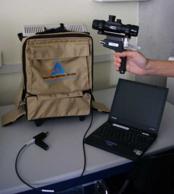
Figure 5.1. ASD FieldSpect Pro-FR Spectroradiometer.
• GER 3700 Spectroradiometer
The GER 3700 Spectroradiometer (fig.5.3), with a spectral range of 300 to 2500 nm, has 704 measurement channels. Spectral resolution of 1.5 nm from 300 to 1050 nm, 6.5 nm from 1050 to 1900 nm and 9.5 nm from 1900 to 2500 nm. Their scan time is 50 ms and it has a field of view (FOV) of 6º circular. Spectrum averaging is selectable from 4 to 9.
Figure 5.2. GER 3700 Spectroradiometer
• Spectralon reference panel
Physical Properties:
• Density: 1.25 - 1.5 g/cm3
• Water Permeability: <0.001% (Hydrophobic)
• Hardness: 20 - 20 Shore D
• Coefficient of Linear Expansion: 5.5 - 6.5 x 10(-5) in/in-F°, 10(-40)C(-1)
• Thermal Stability: to 350°C
• Vacuum Stability: No outgassing except for entrained air
• Flammability: Non-flammable (UL rating V-O)
Spectralon reflectance material is a perfectly diffuse reflecting material
that is ideal for applications ranging from the UV-VIS to the NIR-MIR
wavelength region. Spectralon is a highly lambertian, thermoplastic material
that can be machined into a wide variety of shapes to suit any reflectance
component requirement. Typical applications include back-light illuminators,
lamp housings, integrating spheres, laser cavities and calibration targets.
Three grades of Spectralon reflectance material are available for component
fabrication.
• Transmittance/Radiance images using electronic tunable filters.
Hiperspectral images of leaves and canopy in the VIS and NIR regions are to be acquired using the two main technologies for electronic tunable filters: Liquid Crystal Tunable Filters (LCTF) and Acousto-Optic Tunable Filters (AOTF).
• Description of OKSI LCTF
A LCTF is formed by a stack of polarizers and tunable retardation liquid crystal plates. Combining the transmission of all the plate only a narrow band can be transmitted. Changing the bandpass is very fast (~50 msec). We are using the OKSI hypersepctral camera, which uses two VarisPec Tunable Imaging Filter from Cambridge Research, Inc., one covers the VIS range and the second one the NIR.
Table 5.1.- Charactersitics for tjhe Varispec LCTF
| Spectral
range |
Bandwidth |
|---|---|
| 400-720 nm |
5 nm |
| 650-1050 nm |
7 nm |
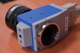
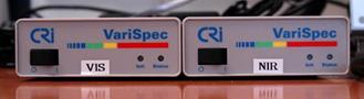
Figure 5.3.VIS filter and the VIS/NIR control units.
• Description of Brimrose AOTF.
The “AOTF Camera Video Adapter CVA-100” from Brimrose is a sealed unit that contains AOTF modular, relay optics, zero-order stop and CCD camera interface. It has a front aperture and a back aperture to connect, respectively, a camera objective and a optical sensor. The optical device is controlled by a AOTF Driver with a frequency range from 69 MHz to 219 MHz. This equipment has the following specifications:
–Aperture size: 10x10 mm.
–Wavelength range: 400 - 1000 nm.
–Spectral resolution: 4.5 nm @ 800 nm.
–Drive frequency: 90 to 210 MHz.
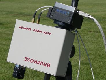
Figure 5.4. Brimrose AOTF Video adapter with a B/W Firewire camera.
• Camera
The camera used to acquire the spectral bands is a 12-bit resolution
Qimaging Retiga EX with the following features:
• 1360x1036 pixels.
• High Quantum efficiency.
• FireWire IEEE 1394 digital interface
• High-Speed low noise electronics
• Exposure/Integration control 40 µ seconds to 15 minutes
• 5 fps in 12-bit mode
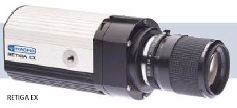
Figure 5.5.Monochrome video camera.
• Illumination.
An illumination box has been built in order to generate a suitable light source for reflectance and transmittance measurements. Halogen lamps, with DC supply, are used. Diffuse lighting is achieved by using both a wide band diffuser and a proper lamp layout that mimics an integration sphere.
Measurement plan
Optical radiometric measurements will be performed with three objectives in mind:
- Radiometric calibration of air and spaceborne sensors imagery.
- Radiometric characterization of main crops in test area.
- Transmittance and reflectance at leaf level under controlled conditions.
For calibration purposes appropriate homogeneous fields will be identified
for measurements in a time-span of one hour before and after the overpass
of sensors, in a daily basis.
Reference fields could be plowed bare soils (if they do not present strong
colour changes), alfalfa fields and dense grass fields. The size of the
fields will be taken into account in order to assure that they at least
double the pixel size of the corresponding sensor each day.
The sampling strategy will be to cover the fields in transects with continuous
measurements, making several stops at random to take white reference radiance
and a larger number of samples of the same spot for greater accuracy.
The radiometers to be used for these measurements will be the ASD-FSFR.
For the characterization of vegetation, a number of significant crops
will be determined in coordination with the teams in charge of vegetation
measurements. In them separate measurements will take place of soil and
canopy under sun and shadows conditions.
The radiometers involved will be the ASD-FSFR, ASD-HH, and GER3700. The
GER will be place on top of a crane in order to measure over tall crops,
with capability for angular measurements.
From these fields, several leaf samples will be collected and preserved
for transmittance and reflectance measurements in the laboratory.
These measurements will take place in a dark room specially set for the
purpose in a building of the ITAP at the test area. An ASD-FSFR will be
used for this purpose together with two experimental imaging radiometer
systems based on optical tuneable filters.
All measurements will be acquired in radiances, and later processed into
reflectances when needed.
UCL Leaf Reflectance/Transmittance and Top-of-Canopy Reflectance Measurements Plan
| Equipment:
|
ASD Fieldspec FR spectroradiometer, ASD leaf grip device, laptop computer, spectralon panel. |
| Leaf Reflectance/Transmittance Protocol:
|
Use ASD leaf grip device which is connected to the ASD contact probe. The leaf grip is fitted with white and black background panels, against a white background panel leaf single scattering albedo is measured, against a black background reflectance is measured. The contact probe has its own light source, so measurements do not have to be made in the field, and is more convenient logistically, if these measurements are made in a laboratory. Because of the size of the port on the ASD contact probe, there must be sufficient leaf area to cover it. In order to achieve this, a number of leaves (each from the same position along the stem, with leaf surface facing the same way i.e. all adaxial or abaxial facing up, so that there is no mixing) will be taped together in order to provide an area large enough to fill the sample port. Clearly, for different species more or less leaves will be required to fill the sample port. Furthermore, the size of the leaves from the various species will influence how easily this procedure can be followed. Leaf reflectance and transmittance measurements will then be made at the base, middle, and top of the leaf sample, by placing the leaf sample between the probe and the panel background. The procedure is repeated for both the abaxial and adaxial surfaces. A note of caution in using the probe is that the light source within the probe soon heats the leaf and leads to burning, such that the measurement needs to be made fairly rapidly. The scan average on the ASD will therefore be set to 15. For each leaf sample (position on stem, and section of leaf (top, middle, base)) up to 3 leaves will be sampled for each leaf position. Given the heating of the leaves by the probe, together with the size of sample required to fill the sample port, it is not really viable to make replicate measurements on the same leaf sample. Between each sample measurements of the white reference panel will be made. |
| Top-of-Canopy Reflectance Measurements:
|
Using the ASD with the fibre-optic extension, and 8 degree fore-optic, measurements of top-of-canopy (TOC) reflectance will be made in each field of crops. For very tall canopies (>2m) a fishing rod may be used in order to be able to get above the canopy, and make the measurements. Measurements of the spectralon panel will be made before TOC measurements are taken, and then again after 3 or 4 TOC reflectance measurements. These TOC measurements will be made at the same points where the biophysical team will be taking samples, wherever and whenever this is possible. |
THERMAL INFRARED GROUND RADIOMETRIC MEASUREMENTS
Instrumentation
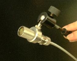
• CIMEL 312-1 radiometer
The CIMEL CE-312-1 is a radiance-based thermal-infrared radiometer composed
of two major components: an optical head containing the detector and optics,
and the electronic unit that performs the data storage. The detector includes
one broad-band filter, 8-13 µm, and three narrower filters, 8.2
– 9.2 µm, 10.5 – 11.5 µm and 11.5 – 12.5
µm (Table 5.1). A external temperature probe can be added by the
user into the control unit. It allows collecting the temperature of an
external blackbody especially for the estimation of absolute emissivity.
A set of different scenarios is available to collect data depending on
the user desires.
Table 5.1. Thermal Infrared radiometer CIMEL CE312 specifications
| Spectral pass-band: |
Channel 1: 8 – 13 µm Channel 2: 11.5 – 12.5 µm Channel 3: 10.5 – 11.5 µm Channel 4: 8.2 – 9.2 µm |
| Temperature range |
– 80 to +50 ºC |
| Operating environment |
– 20 to +50 ºC |
| Resolution |
8 mK for the broad band 50 mK for the other bands (at 20 ºC) |
| Response time |
1 second |
| Field of view |
10º |
| Readout data |
Local display. Transferable on PC |
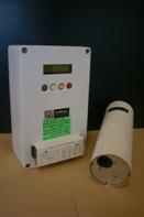
• CIMEL 312-2 ASTER radiometer
The CIMEL CE-312-2 ASTER is a radiance-based thermal-infrared radiometer composed of two major components: an optical head containing the detector and optics, and the electronic unit that performs the data storage. The detector includes 6 bands, a wide one, 8-13 µm, and five narrower filters, 8.1 – 8.5 µm, 8.5 – 8.9 µm, 8.9 – 9.3 µm, 10.3 – 11 µm and 11 – 11.7 µm (Table 5.2). A external temperature probe can be added by the user into the control unit. It allows collecting the temperature of an external blackbody especially for the estimation of absolute emissivity. A set of different scenarios is available to collect data depending on the user desires.
Table 5.2. Thermal Infrared radiometer CIMEL CE312 specifications
| Spectral pass-band: |
Channel 1: 8 – 13 µm Channel 2: 11 – 11.7 µm Channel 3: 10.3 – 11 µm Channel 4: 8.9 – 9.3 µm Channel 5: 8.5 – 8.9 µm Channel 6: 8.1 – 8.5 µm |
| Temperature range |
– 80 to +60 ºC |
| Operating environment |
– 20 to +50 ºC |
| Resolution |
8 mK for the broad band 50 mK for the other bands (at 20ºC) |
| Response time |
1 second |
| Field of view |
10º |
| Readout data |
Local display. Transferable on PC |
• EVEREST 3000.4ZLC Infrared temperature transducer
The Everest thermometer, model 3000.4ZLC single band 8 – 14 µm collect the infrared radiation from the sample converting it into electrical signal. With the suitable calibration process, the electrical signal is converted to a signal in terms of temperature. It is scaled from – 40ºC to 100ºC with a resolution of 0.1 K, an accuracy of ±0.5 K and a repeatibility of ±0.1K. The Field of View -FOV- is 4º. It has an adjustable emissivity equal to unity. The output signal is in mV (10 mV/º), and the power requirements is 5V to 26V DC. Power supply was provided by an auxiliary Einhell power station.
Table 5.3. EVEREST 3000.4ZLC transducer specifications.
| Spectral pass-band: |
Single band: 8–14 µm |
| Operating range |
from – 40º C to 100º C |
| Accuracy |
0.2 K |
| Field of view |
4º |
| Resolution |
±0.5 K |
| Repeatibility |
±0.1 K |
| Other characteristics |
Adjustable emissivity. Transferable on PC. |
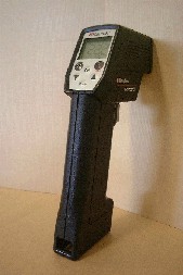
• RAYTEK ST8 Infrared radiometer
A portable RAYTEK, model ST8 single band 8–14 µm, with a FOV of 8 degrees, and with adjustable emissivity operation mode will be used. It ranges up to 100ºC with a sensitivity of 0.1 K and an accuracy of 0.5K. It has a laser beam that helps to locate the target for the measurements.
• RAYTEK Thermalert MID radiometers
The Raytek Thermalert MID radiometer is an infrared sensor with a single band 8–14 µm, with a FOV of 20 degrees, and with adjustable emissivity operation mode. It ranges up to 600ºC with a sensitivity of 0.1 K and an accuracy of 0.5K.
• Thermocouple Type K.
The water and surface temperature measurement will be measured with different
thermocouples with error lower than 0.1 ºC.
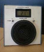
• EVEREST 1000 calibration source
A calibration source EVEREST model 1000 will be used to calibrate the radiometers. Its operating range is from 0ºC to 60ºC, with a resolution of 0.1K, with an absolute accuracy of 0.3 K over entire range.
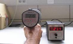
• GALAI 204-P calibration source (from the ULP)
A calibration source GALAI model 204-P will be used to calibrate the radiometers.
• LICOR LI-1000 Dataloggers
Four different Licor LI-1000 dataloggerss will be used to storage data from both radiometers and thermocouples.
CAMPBELL CR21 Micrologger (from the ULP)
The Campbell micrologger is a compact, self-contained datalogger with
Programming capabilities dependent on internal software PROM. It will
be used to storage the radiometers data.
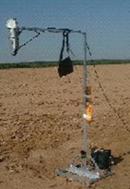
• Goniometer motorized system
A Goniometer with a rotating arm installed to change the observation angle
in the zenith direction, a 1m high elevator to adjust the measuring level
and a half circle roadway to change the observation angle in the azimuth
direction will be used to measure directional brightness temperature.
Details of the instruments are given in Table 5.4.
Table 5.4. Thermal Infrared instrument settings.
Measurement plan
A set of thermal radiometric measurements will be carried out in the
framework of the SPARC-2004 experimental field campaign. The retrieval
of bio geophysical parameters such as land surface emissivity and temperature
is the main aim of these measurements. To this end, radiometric measurements
will be carried out in the thermal infrared region with various instruments
that include fixed FOV and single band or multi bands radiometers. In
addition, a thermocouple for thermometric temperatures measurements and
black bodies (calibration sources) for calibration purposes will be used.
Therefore, the experimental work of the Global Change Unit of the University
of Valencia will be the measurement of thermal radiometric temperatures,
emissivities, atmospheric radiances, air temperature, temperature transects
and angular measurements within the BARRAX area (see Table 5.5). Transects
will be performed concurrently to the flight/satellite overpasses (HyMap,
ROSIS, CHRIS-PROBA, AATSR, LANDSAT, ASTER, METEOSAT MSG (daily). Transects
will be carried out taking temperatures measurements with different field
radiometers (CIMEL, RAYTEK and EVEREST), at regular steps (3 meters) or
fixed in characteristic areas.
Table 5.5. Field work foreseen by Global Change Unit during SPARC-2003.
TBD:
- All days, brightness temperature transects simultaneously with flight/satellite overpass will be carried out (AHS, AATSR, ASTER, SEVIRI, LANDSAT, AIRFLEX).
- All the samples in the table 5.5 are named according to the classification crop map corresponding to 2004.
PLANNED ACTIVITIES:
Table 5.5. Planned activities for the Mission 1 of SEN2FLEX campaign.
| Date |
Sample |
Measurements |
|
31/05/2005 |
Near area of water (UTM: 4324500 N, 578000 W):
· Irrigated crops · Fallow · Non-irrigated crops · Water · Alfalfa · Lysimeter areas.
|
· 10-12 A.M: Assembly of the different measurement instrumental and field crop area recognition. · Afternoon: surface temperature, air temperature and emissivity measurements in Las Tiesas area.
|
|
01/06/2005 |
· Forestry area (UTM: 1332000 N, 601000 W):
|
· Characterization of the forestry canopy: surface temperature, air temperature and emissivity measurements.
|
|
02/06/2005 |
Las Tiesas area (UTM: 4324500 N, 578000 W): · Irrigated crops · Non-Irrigated crops · Alfalfa · Water · Vineyard · Lysimeter areas
|
· Characterization of the different canopies present in the Las Tiesas area: surface temperature, air temperature and emissivity measurements.
|
|
03/06/2005 |
Las Tiesas area (UTM: 4324500 N, 578000 W): · Irrigated crops · Non-Irrigated crops · Alfalfa · Water · Vineyard · Lysimeter areas
|
· Characterization of the different canopies present in the Las Tiesas area: surface temperature, air temperature and emissivity measurements.
|
Goniometer system
EVEREST 3000.4ZLC Infrared temperature transducer
CIMEL 312-1 radiometer
RAYTEK ST6 Infrared radiometer
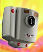
Thermal camera Irisys-Iri1001
EVEREST 1000 calibration source
RAYTEK Thermalert MID radiometers
GALAI 204-P calibration source (from the ULP)
Thermocouple Type K
Goniometer motorized system